[[Wavelength Division Multiplexing - WDM]]
## Optical Fiber Structure
Optical fiber is a medium to carry information. Optical fiber is made of silica-based glass, and consists of a core surrounded by cladding. The central part of the fiber, called the core, has a refractive index of N1. The cladding that surrounds the core has a lower refractive index of N2. When light enters the fiber, the cladding confines the light to the fiber core, and the light travels down the fiber by internal reflection between the boundaries of the core and the cladding.
**Figure 1 – Optical Fiber Structure**
[](https://www.cisco.com/c/dam/en/us/support/docs/optical/synchronous-digital-hierarchy-sdh/29000-db-290005.gif "db_290005.gif")
Optical fibers are broadly classified into two types:
1. single-mode fibers
2. multi-mode fibers
## Single Mode Fibers
Single-mode fiber allows only one mode (or path) for light to travel, directly down the middle of the fiber. The fiber has a small core, typically around 9 microns in diameter. Due to the single light path, it reduces light reflection and allows the signal to travel for longer distances with fewer losses compared to multi-mode fiber. This type of fiber is generally used for long-distance data transmission such as in telecommunication and cable TV networks. The ITU-T G.652 standard is the most common specification for single-mode optical fiber.
## Multi Mode Fibers
Multi-mode fiber allows multiple light modes or paths to travel inside the fiber core, which is considerably larger than that of a single-mode fiber, usually 50 or 62.5 microns in diameter. Multi-mode fibers are used for shorter distances, typically less than 2 kilometers, as the multiple light paths can cause signal distortion over longer distances. These fibers are commonly used in data centers, enterprise networks, and local area networks (LANs).
- **Step-Index Multi-Mode Fiber**: In this type of fiber, the core has a uniform refractive index and there is a sharp decrease as you move to the cladding. This results in different paths (or modes) of light traveling at the same speed.
- **Graded-Index Multi-Mode Fiber**: The refractive index of the core in this type of fiber decreases gradually from the center towards the cladding. This allows light in the outer modes to travel faster than in the central modes, reducing modal dispersion and allowing the signals at the output end to arrive at nearly the same time.
![[Pasted image 20240519210323.png]]
![[Pasted image 20230613142338.png]]
### Types of Fibers by ITU
1. **ITU-T G.652**: This is the standard single-mode optical fiber. It's designed to operate in the 1310nm and 1550nm region and has a very low signal loss at these wavelengths.
2. **ITU-T G.653**: This is dispersion-shifted fiber (DSF). It's designed to minimize chromatic dispersion in the 1550nm region, which was the main issue with G.652 fibers. However, it's rarely used in new installations because it leads to a phenomenon called four-wave mixing in WDM (wavelength division multiplexing) systems.
3. **ITU-T G.654**: This is cut-off shifted fiber (CSF). It's designed to operate effectively at 1550nm and has very low attenuation at this wavelength. It's typically used for long-haul and submarine cable systems.
4. **ITU-T G.655**: This is non-zero dispersion-shifted fiber (NZ-DSF). It's designed to reduce four-wave mixing and still provide a low level of signal dispersion. It's typically used in WDM systems with a large number of channels and high bit rates.
5. **ITU-T G.656**: Also known as Medium Dispersion Fiber (MDF), it's designed for networks which use the wavelengths between 1460nm and 1625nm. It's suitable for long-haul systems that use CWDM and DWDM transmission.
6. **ITU-T G.657**: This is a bend-insensitive fiber. It's designed for use in situations where bending and flexibility are required, like in buildings or other tight spaces.
7. **ITU-T G.661**: This defines the framework for optical fiber and cable test procedures.
----
### Decibels
In optical fiber transmission, decibels (dB) are used to measure the ratio between two power levels. Specifically, they represent losses, gains, and attenuation in the optical signals transmitted through the fiber. Decibels provide a logarithmic scale, which simplifies the representation of large variations in signal power. This measurement is crucial for understanding the performance and efficiency of the fiber optic system, as it helps in calculating power transmission losses and designing effective communication links.
## Wavelength
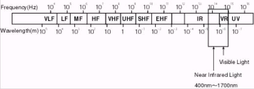
A small amount of light is injected into the fiber. This falls into visible wavelength (from 400nm to 700nm) and near infrared wavelength (from 700nm to 1700nm) in the electromagnetic spectrum.
**Figure 3 – The Electromagnetic Spectrum**
[](https://www.cisco.com/c/dam/en/us/support/docs/optical/synchronous-digital-hierarchy-sdh/29000-db-290007.gif "db_290007.gif")
There are four special wavelengths that you can use for fiber optic transmission with low optical loss levels, which this table lists:
| Windows | Wavelength | Loss |
| -------------- | --------------- | -------- |
| 1st wavelength | 850nm | 3dB/km |
| 2nd wavelength | 1310nm | 0.4dB/km |
| 3rd wavelength | 1550nm (C band) | 0.2dB/km |
| 4th wavelength | 1625nm (L band) | 0.2dB/km |